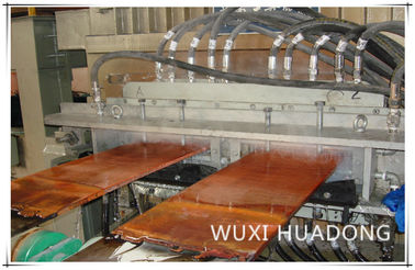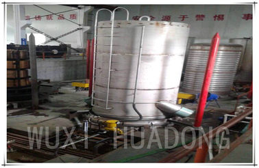


Up Ward Continuous Casting Machine is a new technology to produce oxygen free copper rod, tube, and flat billet at a rewet length. Its production of oxygen free copper rod and profiles and featured with high conductivity and low oxygen content. Compare with some traditional technology. This new method is lower in capital investment, easy to operate with, economic in producing. high qulity in production, flexible in changing production size no pllution to eviroment.
Copper cathode (panel) →induction furnace(copper melt→reduction→molten copper holding)→casting mechanism casts rod (copper crstalize and become solild)→Take-up→Sale productionor for further process.
| 1 | Smelting furnace: | |
| 1.1 | Total capacity of furnace | 5.0T |
| 1.2 | Effective capacity of furnace | 2.5T |
| 1.3 | Furnace voltage | 380V |
| 1.4 | Furnace power | 600KW |
| 1.5 | Melting rate | 2t/h |
| 1.6 | Power factor after compensation: | 0.95-1.0 |
| 1.7 | Number of phases and connection mode of inductor: | Single-phase series-connection |
| 1.8 | Rated capacity of transformer: | 900KVA water-cooled autotransformer (380V incoming-line, three-phase, |
| 1.9 | coil cooling mode: | Water-cooling |
| 1.10 | Cooling water consumption: | 5m3/h |
| 1.11 | Maximum temperature of furnace: | 1500℃ |
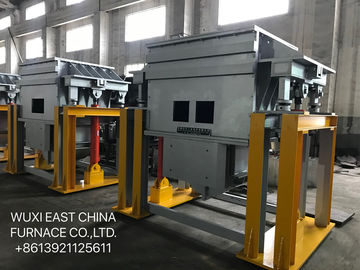
| 2 | Holding furnace section | |
| 2.1 | Effective capacity of furnace: | 4.0T |
| 2.2 | Effective casting capacity: | Less than 85 dB |
| 2.3 | Rated voltage: | 380V |
| 2.4 | Rated power : | 250KW |
| 2.5 | Rated capacity of transformer: |
400KVA water-cooled autotransformer (380V incoming-line, three-phase, no-load stepped voltage-regulating). |
| 2.6 | Power factor after compensation: | 0.95-1.0 |
| 2.7 | Temperature control precision: | ±8℃ |
| 2.8 | Maximum temperature of furnace: | 1300℃ |
| 2.9 | Coil cooling mode: |
Water-cooling |
| 3 | Mould | |
| 3.1 | width | 330- 500mm |
| 3.2 | thickness | 16-20mm. |
| 3.3 | Material | 1Cr18Ni9Ti stainless steel, lined with copper bush (made of T2 copper) |
| 4 | Secondary cooling device | |
| 4.1 | Water consumption: | 3m ³/h |
| 4.2 | Water pressure: | 0.2-0.3Mpa |
| 5 | Withdrawal machine | |
| 5.1 | Maximum pushing and drawing force: | 50KN |
| 5.2 | Speed: | Speed: |
| 5.3 | Minimum stroke range: |
0.1mm |
| 5.4 | Shortest standby time | 0.01S |
| 5.5 | AC servo motor: | Sieens motor (11KW) |
| 5.6 | Rated rotation speed of motor: | 3000r/min |
| 5.7 | Static torque: | △Tw= 60K Mo (at 60) 70N-M |
| 6 |
Double-billet hydraulic upper shearing machine:
|
|
| 6.1 | Shearing force: | 600KN |
| 6.2 | shearing thickness: | 20mm |
| 6.3 | Shearing width: | 500mm |
| 6.4 | Shearing speed: |
0- 5mm/s |
| 6.5 | Shearing stroke: | 80mm |
| 6.6 | Maximum follow-up stroke of shearing machine: | 200mm |
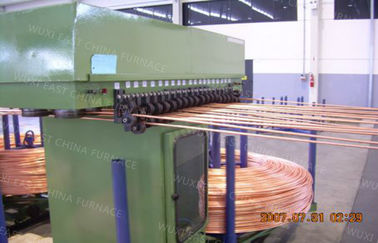
| 7 | Coiler machine unit | |
| 7.1 | Power: | 5.5KW |
| 7.2 | Rotational speed: | 1420r/min |
| 7.3 | Coiler displacement stroke: | 800mm |
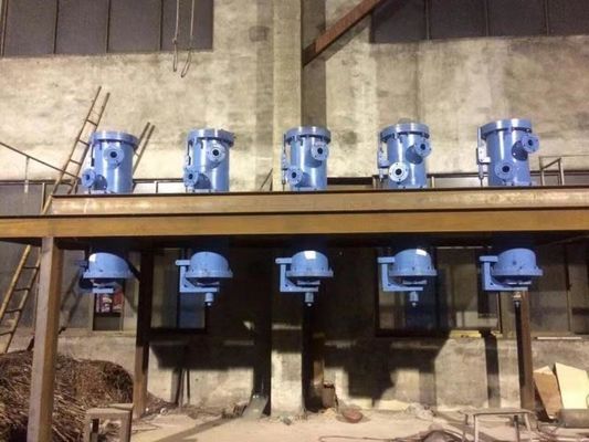
| 8 | Hydraulic station | |
| 8.1 |
Motor power of hydraulic station for smelting furnace and holding furnace:
|
2* 7.5KW |
| 8.2 | Motor power of hydraulic station for withdrawal machine: | 2* 7.5KW |
| 8.3 | Motor power of hydraulic pump for upper shearing machine: |
2* 11KW
|
| 8.4 | Motor power of hydraulic pump for coiler: | 2* 7.5KW |
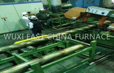
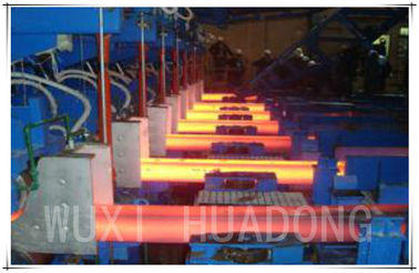
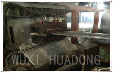
Burdening (Returns should be baled) → Smelting furnace → Chemical analysis → Heating up the sealed launder → Crystallizer → Primary cooling → Secondary cooling → Withdrawal machine → Shearing machine →Coiler
Select the raw materials according to process document, determine the feeding procedure according to melting points of metallic elements, furnace burden proportions, and difficulty of oxidation burning losses, and charge the raw material into the smelting furnace; When smelting, add certain thickness of covering agent into the furnace, which shall be supplemented in-time; When the molten copper inside the furnace reaches tapping temperature, lab-test the composition of molten copper inside the furnace; Before tapping, completely clean out the clinkers in molten copper; After the tapping of each furnace, keep around 800 kg molten copper inside the furnace, as the starting block. Transfer the molten copper (molten and well-adjusted in the melting chamber) through the sealed launder into the holding furnace, control the temperature of molten copper, keep the molten copper inside the holding furnace at the casting temperature and at certain level range. Under the action of level, the molten copper flows into the crystallizer, and get crystallized into plate-type copper billet through primary cooling by crystallizer. Under the continuous drawing by withdrawal machine, the plate billet of required shape is formed. Secondary cooling system is installed at plate billet outlet, and the flow rate of cooling water is adjustable. The main purpose for adopting these control measures is to ensure crystallization temperature as well as stabilization of process parameters, so as to ensure product quality. The withdrawal of strip billet is realized by means of the dragger, and the time of drawing, stop and reverse pushing by the dragger is continuously adjustable. The optimal control parameter should be determined and timely adjusted according to different materials, different specifications and surface quality conditions. The drawing is controlled by PLC program, realizing cyclical actions of drawing, stop, and reverse pushing.
![]()
![]()
![]()
| No. | Equipment Name | Unit | QTY |
| 1 | Line frequency induction smelting furnace (including melting groove and lining building material) | set | 1 |
| 2 | Iron core, water jacket and coil of smelting furnace | set | 1 |
| 3 | Tundish | set | 1 |
| 4 | Line frequency induction holding furnace (including melting groove and lining building material) | set | 1 |
| 5 | Iron core, water jacket and coil of holding furnace | set | 1 |
| 6 | mould for lining building | set | 1 |
| 7 | crystallizer | set | 2 |
| 8 | graphite mould | set | 1 |
| 9 | Sealing steel mould of crystallizer | set | 1 |
| 10 | Dummy bar (made of stainless steel) | set | 1 |
| 11 | Dummy plate | set | 1 |
| 12 | Cooling water distribution device for crystallizer | set | 1 |
| 13 | Secondary cooling device | set | 1 |
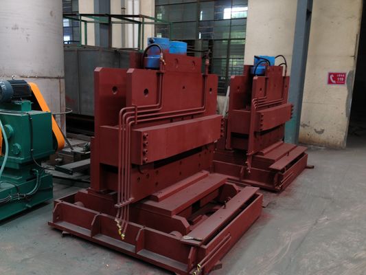
| 14 | Withdrawal machine | set | 1 |
| 15 | Hydraulic follow-up shearing machine | set | 1 |
| 16 | Coreless coiler | set | 2 |
| 17 | Water-cooled cable for smelting furnace | set | 1 |
| 18 | Hydraulic system | Complete set | 1 |
| 19 | Electrical control system | Complete set | 1 |
| 20 | Regulating transformer (no-load, stepped) for smelting furnace | set | 1 |
| 21 | Regulating transformer (no-load, stepped) for holding furnace | set | 1 |
| 22 | Gas protection device | set | 1 |
| 23 | Surface temperature thermometer | set | 1 |
| 24 | Special tools for machine unit |
![]()
![]()